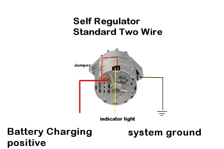
Wiring Diagram of Alternator

In the heart of every vehicle’s electrical system lies a critical component that ensures a continuous flow of power: the alternator. The alternator plays a pivotal role in generating electrical energy, charging the battery, and powering various electrical systems in the vehicle. To understand the intricate dance of electrons within this powerhouse, one must unravel the secrets of its wiring diagram.
The Anatomy of an Alternator:
Before delving into the wiring diagram, it’s essential to grasp the basic structure of an alternator. Unlike its predecessor, the dynamo, an alternator is a more efficient and robust device for generating electrical power. An alternator consists of key components such as the rotor, stator, diode rectifier, voltage regulator, and, of course, the wiring system that connects these elements.
Deciphering the Wiring Diagram:
- Rotor and Stator Connection:
- The heart of the alternator lies in the connection between the rotor and stator. The rotor, usually in the form of a coil or a set of magnets, spins within the stator – a stationary coil of wire. This rotation induces an alternating current (AC) in the stator.
- Diode Rectifier Bridge:
- Once the stator generates AC, the diode rectifier bridge steps in to convert it into direct current (DC). The rectifier bridge, typically composed of six diodes arranged in a specific pattern, rectifies the AC into a unidirectional flow of electrons.
- Voltage Regulator:
- To prevent overcharging and ensure a steady supply of power, the alternator employs a voltage regulator. The wiring from the diode rectifier bridge leads to the voltage regulator, which monitors the voltage level and adjusts the field current in the rotor accordingly.
- Output Terminal:
- The final piece of the puzzle is the output terminal, where the now-rectified and regulated DC is sent to charge the vehicle’s battery and power the various electrical systems.
Color-Coded Wires:
Understanding the color-coded wiring system is crucial for proper installation and troubleshooting:
- Red/Orange: Connects to the battery’s positive terminal, supplying power.
- Black: Ground wire, establishing a connection to the vehicle’s chassis.
- Yellow: Links to the ignition switch, activating the alternator when the vehicle starts.
- Blue: Often connects to the dashboard light, indicating alternator activity.
Conclusion:
The wiring diagram of an alternator unveils the intricacies of how this critical component transforms mechanical energy into electrical power, sustaining the lifeblood of a vehicle’s electrical system. As technology advances, variations in wiring diagrams may emerge, but the fundamental principles remain consistent. Armed with this knowledge, both seasoned mechanics and curious car enthusiasts alike can appreciate the symphony of electrons within the alternator, ensuring the smooth operation of our beloved vehicles.


